


The two most common unshielded twisted-pair (UTP) network standards are the10 Mhz 10BASE-T Ethernet and the 100Mhz 100BASE-TX Fast Ethernet. The 100BASE-TX standard is quickly becoming the predominant LAN standard. If you are starting from scratch, to build a small home or office network, this is clearly the standard you should choose. This article will show you how to make cables which will work with both standards.
ABOUT LAN :- A LAN can be as simple as two computers, each having a network interface card (NIC) or network adapter and running network software, connected together with a crossover cable.
The next step up would be a network consisting of three or more computers and a hub. Each of the computers is plugged into the hub with a straight-thru cable (the crossover function is performed by the hub).

 About cables and connector :- CAT 5 cable has four twisted pairs of wire for a total of eight individually insulated wires. Each pair is color coded with one wire having a solid color (blue, orange, green, or brown) twisted around a second wire with a white background and a stripe of the same color. The solid colors may have a white stripe in some cables. Cable colors are commonly described using the background color followed by the color of the stripe; e.g., white-orange is a cable with a white background and an orange stripe.
 The straight through and cross-over patch cables discussed in this article are terminated with CAT 5 RJ-45 modular plugs. RJ-45 plugs are similar to those you'll see on the end of your telephone cable except they have eight versus four or six contacts on the end of the plug and they are about twice as big. Make sure they are rated for CAT 5 wiring. (RJ means "Registered Jack"). Also, there are RJ-45 plugs designed for both solid core wire and stranded wire. Others are designed specifically for one kind of wire or the other. Be sure you buy plugs appropriate for the wire you are going to use. I use plugs designed to accommodate both kinds of wire.

Modular Plug Crimp Tool. You will need a modular crimp tool. This one is very similar to the one I have been using for many years for all kinds of telephone cable work and it works just fine for Ethernet cables. You don't need a lot of bells and whistles, just a tool which will securely crimp RJ-45 connectors. Even though the crimper has cutters which can be used to cut the cable and individual wires, and possibly stripping the outer jacket, I find that the following tools are better for stripping and cutting the cable.
 COLOR-CODE STANDARDS :-Let's start with simple pin-out diagrams of the two types of UTP Ethernet cables and watch how committees can make a can of worms out of them. Here are the diagrams:
 Note that the TX (transmitter) pins are connected to corresponding RX (receiver) pins, plus to plus and minus to minus. And that you must use a crossover cable to connect units with identical interfaces. If you use a straight-through cable, one of the two units must, in effect, perform the cross-over function.
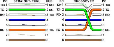 Note that pins 4, 5, 7, and 8 and the blue and brown pairs are not used in either standard. Quite contrary to what you may read elsewhere, these pins and wires are not used or required to implement 100BASE-TX duplexing--they are just plain wasted.
Now, all you need to remember, to properly configure the cables, are the diagrams for the two cable ends and the following rules:
1. Pull the cable off the reel to the desired length and cut.
2. Spread and arrange the pairs roughly in the order of the desired cable end.
3. Untwist the pairs and arrange the wires in the order of the desired cable end. Flatten the end between your thumb and forefinger. Trim the ends of the wires so they are even with one another. It is very important that the unstripped (untwisted) end be slightly less than 1/2" long. If it is longer than 1/2" it will be out-of-spec and susceptible to crosstalk. If it less than slightly less than 1/2" it will not be properly clinched when RJ-45 plug is crimped on.. Flatten again. There should be little or no space between the wires.

 Hold the wire near the RJ-45 plug with the clip down and firmly push it into the left side of the front of the crimper (it will only go in one way). Hold the wire in place squeeze the crimper handles quite firmly. This is what will happen:
 (Crimp it once.) The crimper pushes two plungers down on the RJ-45 plug. One forces what amounts to a cleverly designed plastic plug/wedge onto the cable jacket and very firmly clinches it. The other seats the "pins," each with two teeth at its end, through the insulation and into the conductors of their respective wires.
Test the crimp...
If done properly an average person will not be able to pull the plug off the cable with his or her bare hands. And that quite simply, besides lower cost, is the primary advantage of twisted-pair cables over the older thinwire, coaxial cables. In fact, I would say the RJ-45 and ease of its installation is the main reason coaxial cable is no longer widely used for small Ethernets. But, don't pull that hard on the plug. It could stretch the cable and change its characteristics. Look at the side of the plug and see if it looks like the diagram and give it a fairly firm tug to make sure it is crimped well.
ABOUT LAN :- A LAN can be as simple as two computers, each having a network interface card (NIC) or network adapter and running network software, connected together with a crossover cable.
The next step up would be a network consisting of three or more computers and a hub. Each of the computers is plugged into the hub with a straight-thru cable (the crossover function is performed by the hub).

 About cables and connector :- CAT 5 cable has four twisted pairs of wire for a total of eight individually insulated wires. Each pair is color coded with one wire having a solid color (blue, orange, green, or brown) twisted around a second wire with a white background and a stripe of the same color. The solid colors may have a white stripe in some cables. Cable colors are commonly described using the background color followed by the color of the stripe; e.g., white-orange is a cable with a white background and an orange stripe.
 The straight through and cross-over patch cables discussed in this article are terminated with CAT 5 RJ-45 modular plugs. RJ-45 plugs are similar to those you'll see on the end of your telephone cable except they have eight versus four or six contacts on the end of the plug and they are about twice as big. Make sure they are rated for CAT 5 wiring. (RJ means "Registered Jack"). Also, there are RJ-45 plugs designed for both solid core wire and stranded wire. Others are designed specifically for one kind of wire or the other. Be sure you buy plugs appropriate for the wire you are going to use. I use plugs designed to accommodate both kinds of wire.
Modular Plug Crimp Tool. You will need a modular crimp tool. This one is very similar to the one I have been using for many years for all kinds of telephone cable work and it works just fine for Ethernet cables. You don't need a lot of bells and whistles, just a tool which will securely crimp RJ-45 connectors. Even though the crimper has cutters which can be used to cut the cable and individual wires, and possibly stripping the outer jacket, I find that the following tools are better for stripping and cutting the cable.
 COLOR-CODE STANDARDS :-Let's start with simple pin-out diagrams of the two types of UTP Ethernet cables and watch how committees can make a can of worms out of them. Here are the diagrams:
 Note that the TX (transmitter) pins are connected to corresponding RX (receiver) pins, plus to plus and minus to minus. And that you must use a crossover cable to connect units with identical interfaces. If you use a straight-through cable, one of the two units must, in effect, perform the cross-over function.
 Note that pins 4, 5, 7, and 8 and the blue and brown pairs are not used in either standard. Quite contrary to what you may read elsewhere, these pins and wires are not used or required to implement 100BASE-TX duplexing--they are just plain wasted.
Now, all you need to remember, to properly configure the cables, are the diagrams for the two cable ends and the following rules:
- A straight-thru cable has identical ends
- A crossover cable has different ends.
1. Pull the cable off the reel to the desired length and cut.
2. Spread and arrange the pairs roughly in the order of the desired cable end.
3. Untwist the pairs and arrange the wires in the order of the desired cable end. Flatten the end between your thumb and forefinger. Trim the ends of the wires so they are even with one another. It is very important that the unstripped (untwisted) end be slightly less than 1/2" long. If it is longer than 1/2" it will be out-of-spec and susceptible to crosstalk. If it less than slightly less than 1/2" it will not be properly clinched when RJ-45 plug is crimped on.. Flatten again. There should be little or no space between the wires.

 Hold the wire near the RJ-45 plug with the clip down and firmly push it into the left side of the front of the crimper (it will only go in one way). Hold the wire in place squeeze the crimper handles quite firmly. This is what will happen:
 (Crimp it once.) The crimper pushes two plungers down on the RJ-45 plug. One forces what amounts to a cleverly designed plastic plug/wedge onto the cable jacket and very firmly clinches it. The other seats the "pins," each with two teeth at its end, through the insulation and into the conductors of their respective wires.
Test the crimp...
If done properly an average person will not be able to pull the plug off the cable with his or her bare hands. And that quite simply, besides lower cost, is the primary advantage of twisted-pair cables over the older thinwire, coaxial cables. In fact, I would say the RJ-45 and ease of its installation is the main reason coaxial cable is no longer widely used for small Ethernets. But, don't pull that hard on the plug. It could stretch the cable and change its characteristics. Look at the side of the plug and see if it looks like the diagram and give it a fairly firm tug to make sure it is crimped well.


